6 August 2026: the engine spine, the whole sprite system, and the mode handlers
The longest day so far, seventeen sessions (4 to 20) in bank $C0. The game loop and its per-frame reset are matched, then the complete sprite system, from the VBlank handler down to every renderer and init helper, then the head of the per-frame state machine and all five of its named mode handlers: 9,542 new bytes in 32 functions.
Terms like OAM, DMA, BRL and the M and X flags are in the Glossary.
GameLoop: the engine spine
GameLoop starts at $C0:000E, right where MainInit hands over. In order, it:
- installs RAM-resident NMI and IRQ handlers (explained below)
- sets the Direct Page to
$0100, so dp variables live at WRAM$0100–$01FF - calls
InitHWto turn off all hardware output (forced blank, no NMI, no DMA) - clears about 80 KB of WRAM with DMA
- calls engine subsystem init routines in banks
$C7and$C2 - falls into
GameLoop_Main, the per-frame loop
The table at $C0:0000. Before GameLoop there is a 14-byte table at the very start of bank $C0:
BRA GameLoop_Main   ; warm restart (skip one-time init)
BRL $2C3C           ; alternate cold start path 1
BRL $0AF7           ; alternate cold start path 2
BRL $1BA0           ; alternate cold start path 3
BRL $1BD8           ; alternate cold start path 4
Entry 0 is a warm restart: it skips the one-time RAM clear and goes straight to the mode dispatch. At first I read entries 1–4 as other boot paths. (The next day showed they are re-entry vectors for other banks, and the table was renamed ReentryVectors.)
The per-frame loop. After init, execution reaches GameLoop_FrameBody at $C0:0097. Every frame it calls, in order:
JSR $18D9    — unknown
JSR $0C76    — unknown
JSR $881E    — unknown
JSR $1AAC    — unknown
JSL $C01F87  — cross-bank call (audio?)
JSR $21E1    — unknown
JSR $274D    — unknown
JSR VBlankHandler    — sync to VBlank
JSR $EC60    — post-VBlank work
BRA GameLoop_FrameBody   — loop forever
The game mode (battle, overworld, menu and so on) lives at WRAM $0100 as a 16-bit index. GameLoop_Main reads it and jumps to the right handler before entering the frame loop.
InitHW, InstallNMI, InstallIRQ
Three small routines that always appear together:
InitHW(22 bytes) turns everything off: forced blank (INIDISP = $80), no NMI/IRQ/auto-joypad (NMITIMEN = $00), no DMA (MDMAEN = $00), no HDMA (HDMAEN = $00). It runs before any hardware state change.InstallNMI(17 bytes) writes the 4-byte instruction5C 63 EA C0to WRAM$7E:0500: aJMLto the real NMI handler at$C0:EA63. The ROM stubs at$00:FF10and$00:FF14just doJML $000500andJML $000504, so the real handlers live in WRAM and are installed here at run time.InstallIRQ(17 bytes) does the same forJML $C0:ECCCat$7E:0504.
The handlers live in RAM because their behavior has to change with what the game is doing. Swapping one JML in WRAM is easier than switching between several ROM handlers.
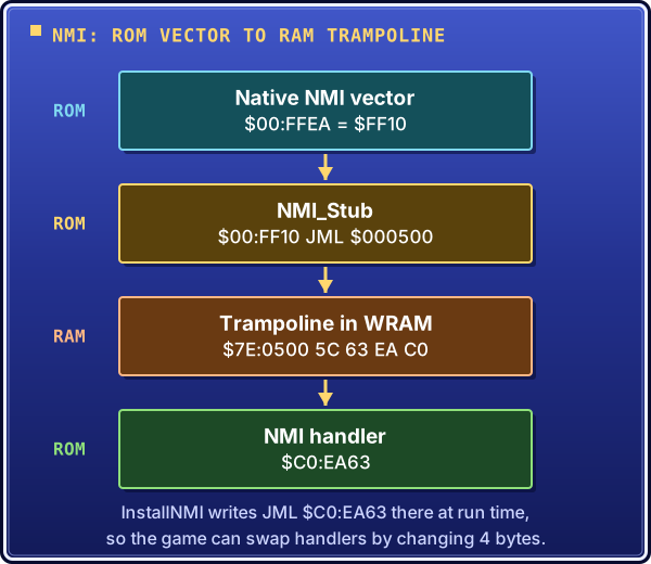
The path an NMI takes: the vector points at a ROM stub, the stub jumps into WRAM, and the four bytes InstallNMI wrote there jump to the real handler.
ClearRAMDMA: a zero-fill with no loop
ClearRAMDMA at $C0:2DF1 (45 bytes) fills WRAM with zeros using the multiply unit:
- set Mode 7 matrix values
M7A = 0andM7B = 0, so their product is 0 - the low byte of the product is readable at
MPYL($2134) - point DMA channel 7 at
MPYLas the source and a WRAM range as the destination - start the DMA
The DMA fills the range with zeros with no STZ loop on the CPU, which is much faster. GameLoop calls it three times:
$7E:0000–$7E:04FF, skipping$0500–$06FFwhere the NMI/IRQ handlers live$7E:0700–$7E:FFFF$7F:5080–$7F:A0FF
The gap at $0500–$06FF is on purpose: InstallNMI and InstallIRQ run before the clear, so the handlers survive it.
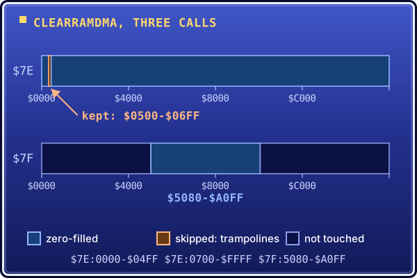
What the three ClearRAMDMA calls clear: nearly all of bank $7E, minus the $0500-$06FF gap that holds the freshly installed trampolines, and $7F:5080-$A0FF.
VBlankHandler: a tail call
VBlankHandler at $C0:00BF calls some audio and DMA routines, then ends like this:
BRL is an unconditional jump, not a call. The JSR VBlankHandler that got here left a return address on the stack ($C0:00BA). Instead of returning, VBlankHandler jumps to PostVBlank, and PostVBlank's RTS uses that saved address to return to JSR $EC60 in the frame loop. This is a tail call: it reuses the caller's return address, saving a stack slot and an instruction.
PostVBlank: OAM buffer culling
PostVBlank at $C0:B271 (152 bytes) manages the sprite buffer for the frame. The SNES PPU has 128 sprite slots. During the frame, game code fills a WRAM buffer with sprite data. During VBlank the buffer goes to the PPU and unused slots get $E0 in their Y byte. Y = $E0 = 224 is below the 224-line visible screen, which hides them.
PostVBlank:
- sets up buffer write-head pointers in dp variables (
$89,$81,$85and others) - walks a sprite descriptor table at WRAM
$0E00(up to 63 slots, 2 bytes each) - calls
Sub_B309for each active sprite to copy it into the right OAM buffer region - fills unused slots in each region with Y =
$E0 - updates the write-head pointers for the next frame
FrameStateInit: the per-scene reset
FrameStateInit at $C0:0B86 (240 bytes) starts at the byte right after InstallIRQ ends ($0B85). GameLoop_Main calls it at the top of each scene iteration. It first saves three sprite registers:
LDX $00     ; active sprite X position
STX $0A     ; save to "previous frame" slot
LDX $02     ; active sprite Y
STX $0C
LDA $04     ; sprite attribute byte
STA $0E
Then about 25 STZ instructions clear per-frame flags and counters ($10, $11, $17, $18, $38, $0F and more). It sets the default off-screen sprite Y to $E0 and resets the OAM write heads to their full-buffer limits ($0900, $0770, $08A0).
A 16-bit section seeds four palette/color-effect parameters from bank $E4 at $FFE0–$FFE6. That is the vector area of bank $E4, which the game reuses as a data table:
REP #$20            ; A -> 16-bit
LDA.l $E4FFE0       ; load 16-bit seed
STA $AF
LDA.l $E4FFE2
STA $B2
; ... two more
Then it zeroes $7E:2000 (a long store, 2 bytes) and goes back to 8-bit A. A dozen more defaults follow ($97, $99, $9B and others all get $80). It reads three dynamic color values from $7E:2980–$2982 into dp $94–$96, zeroes $0BD9, $0BDA, $0BDB and $0BE9, loads a scene entry point from $0400 into $F8, and returns.
With this, the matched code covers the whole engine skeleton: boot, init, game loop, per-VBlank work and per-frame reset.
asar quirks found today
- Named register equates assemble as long addresses.
STA INIDISP(INIDISP = $2100) assembled to8F 00 21 00(4-byte longSTA) instead of8D 00 21(3-byte absolute). One extra byte per register write shifts every address after it. Fix:STA.w INIDISPforces 16-bit addressing. $0001,Xbecomes direct page. asar sees$0001as fitting in 8 bits and picksdp,X($95 $01, 2 bytes) instead ofabs,X($9D $01 $00, 3 bytes). Fix:STA.w $0001,X.STXrejects equate names.STX A1T7L(A1T7L = $4372) gives "Unknown command". LikeJSRwith named labels. Fix: the raw address,STX $4372.BRLstores the raw offset.BRL $B193stores$B193as the operand; it is not the target. The offset is(target - next_PC) & $FFFF. For wrap-around branches, asar's label-basedBRLfails with "branch out of range", so the offset has to be computed by hand. In general,BRLacrossorgblocks needs the raw offset. Inside oneorgblock a local label works.- Asar tracks the M flag in file order. It follows
REP/SEPthrough the whole file, not perorgblock. This bitSub_1B36later in the day (see the mode-$E6 handler below).
Docs: hover definitions and the architecture page
The site now has Wikipedia-style hover definitions. Whenever a page mentions OAM, HiROM, NMI, BRL, asar and so on, hovering (or tapping on mobile) shows the definition. It uses MkDocs Material's abbr extension with pymdownx.snippets auto_append: one abbreviations file defines all 28 terms, and they are applied everywhere with no tagging on individual pages.
The architecture doc now describes the engine flow from matched code only: boot sequence, game loop, VBlank handler, PostVBlank, FrameStateInit, the RAM-resident NMI/IRQ pattern, key data structures and the dp variable table.
The sprite renderer
Sub_B701: the render gate
Sub_B309 opens with JSR $B701 / BCC skip, so Sub_B701 decides whether anything is drawn at all. I matched the gate first.
It reads a state byte from $1B00,X (X is the sprite descriptor index from $6D) and dispatches on the sprite type, bits 0–1 of $1201,X. The carry flag is the answer: C=0 means "render", C=1 means "skip". Sub_B309 checks it with BCC $B30F.
type 0: state=0 → C=1 (skip); positive → run init, mark $80; negative → re-init or done
type 1: same but threshold is 2 (not 0), uses different JSR targets
type 2: threshold 3, uses $C2BF/$EA1F/$BFF2
type 3+: BRL $C73A to a separate renderer
The state byte encodes the sprite's life cycle:
$00: inactive, always C=1- positive, below the type's threshold: partly initialized, skip
- positive, at or above the threshold: run the init routines, set the state to
$80, render - exactly
$80: fully initialized and ready - negative with any of bits 0–6 set: run init again (a partial mid-init state)
A correction later the same day. My first reading made Sub_B701 171 bytes, with an inline type 3+ path that was a byte-identical copy of type 2, and $B788 a trick entry point 3 bytes into that copy that just returned C=0. The bytes said otherwise. Type 3+ is a 3-byte BRL $C73A to a separate renderer, so Sub_B701 is 135 bytes, ending at $B787. And Sub_B788 is a real renderer, called from the type 0 path when the state is exactly $80. The diff confirmed both routines byte-exact after the correction.
Sub_B309: staging buffer to OAM
Sub_B309 at $C0:B309 (1,016 bytes) is the routine PostVBlank calls for every active sprite descriptor. It reads sprite data from a staging buffer in bank $7F and writes it into the OAM buffer in WRAM, which later goes to the PPU. Two hardware tricks are layered inside it.
Trick 1: DP = $2100. Near the top of each type path:
With DP at $2100, direct-page instructions hit PPU registers instead of WRAM. STA $80 writes $2180 (WMDATA, the WRAM write port), and STX $81 writes a 16-bit value to $2181–$2182 (WMADDL/H, the WRAM write address). The routine writes palette data to WRAM without full 3-byte addresses. PLD at the end of each path restores DP to $0100.
Trick 2: a staging buffer in bank $7F. Sprite data is pre-built in WRAM bank $7F, at addresses like $7F:4F00+X and $7F:4BC0+X. The render paths use long (BF) loads to pull bytes from there.
Structure: 4 sprite types × 3 OAM ranges.
- Sprite type (bits 0–1 of
$1201,X) sets how many OAM bytes a sprite uses per slot (1/2/3/6 for types 0/1/2/3+) and how much palette data to copy (4/8/12/24 iterations). - OAM range (bits 2–3 of
$0F80,X) picks one of three buffer ranges: write heads$0181/$0185/$0189, WRAM destinations$01DB/$01DD/$01DF.
Each type path has three range sub-paths that join a shared sprite-graphics and palette loop. For types 1/2/3+, ranges 2 and 3 are too far for a short BRA, so they go through BRL trampolines. The 65816 has no long conditional branch, so the code bounces:
BIT #$04        ; test bit 2 of flag byte
BNE +3          ; branch to next BRL if bit is set (can't BNE long)
BRL range3      ; otherwise: bit 3 only → range 3
BRL range2      ; trampoline target: bit 2 was set → range 2
range1:         ; fall-through: no bits → range 1
The type paths start at $B329 (type 0: sets DP=$2100, reads $7F:4F00+X, writes via the OAM pointer at $0181 and to $01DB), $B3DF (type 1), $B4B8 (type 2) and $B5AF (type 3+). The type 3+ BRL in Sub_B701 led to a new callee, Sub_C73A, added as a stub at first.
Sub_B788: the type 0 renderer, and the DB = $7F trick
Sub_B788 (322 bytes, three exit paths) builds per-tile X and Y positions into the $7F:4BXX table that Sub_B309 later copies into OAM. It starts by switching the data bank:
With DB = $7F, every default-bank instruction (abs, abs,X, abs,Y) reaches WRAM bank $7F without a 3-byte long address: LDA.w $4BC2,X reads $7F:4BC2+X. Every exit restores the bank with SEP #$20 / PLB before RTS. Loads that need a specific bank still use long addressing: LDA.l $000A80,X always reads bank $00.
Prologue. Reads three 16-bit values from bank $00 sprite tables:
LDA.l $000A80,X  AND #$01FF → STA $C5  ; 9-bit position value (C5=lo, C6=hi bit)
LDA.l $000A00,X             → STA $C3  ; base X coordinate
LDA.l $001700,X             → STA $D9  ; sprite gfx index
X-position loop. Walks from gfx_index + $18 down to gfx_index in steps of 8, writing per-tile X bytes to $4BC0,X:
CLC / ADC #$0018            ; start at gfx+$18
.loop:
TAX
LDA.w $4BC2,X / CLC / ADC $C3   ; add base X to tile X offset
SEP #$20
STA.w $4BC0,X                    ; store low byte
XBA / AND #$01 → $E6             ; extract overflow bit
LDA $E5 / ASL / ASL / ORA $E6 → $E5   ; pack flip+overflow bits
CPX $D9 → BEQ .post_loop        ; done when X == gfx_index
STA $E5 / REP #$20 / TXA / SEC / SBC #$0008 / BRA .loop
.post_loop:
ORA #$AA                         ; set attribute bits
LDX $6D / STA.w $4F00,X          ; write to OAM slot
Y dispatch. Three paths on the 9-bit position value:
| Condition | Path | Clamp logic |
|---|---|---|
$C6 ≠ 0 (bit 8 set) |
5-tile loop | BCC .clamp / CMP #$E0 / BCS .store / LDA #$E0 |
$C6 = 0, $C5 ≥ $80 (BMI) |
4-tile loop | BCC .store / CMP #$E0 / BCC .store / LDA #$E0 |
$C6 = 0, $C5 < $80 (BPL) |
4-tile loop | BPL .store / CMP #$E0 / BCS .store / LDA #$E0 |
The $C6 ≠ 0 path writes 5 tile Y positions ($4BC1/$4BC9/$4BD1/$4BD9/$4BE1); the other two write 4.
Sub_C6E7: packing the OAM high-table byte
Sub_C6E7 at $C0:C6E7–$C739 (83 bytes) is the X-position helper for the type 3+ renderer, and was the only thing blocking it. One call handles 4 tiles. For each tile it:
- reads the raw X offset from the
$7F:4BC2/CA/D2/DAstaging buffer (16-bit, M=0) - adds the sprite's base X (
$C3, also 16-bit) - switches to 8-bit (
SEP #$20) and stores the low byte at$7F:4BC0/C8/D0/D8 - takes the overflow bit with the
XBA / AND #$01idiom (afterXBAthe high byte is in A, and bit 0 is X bit 8) - saves the bit in
$E5/$E6/$E7
Then it packs them:
AND #$01        ; tile 4 overflow bit in A
ASL A           ; shift up for packing
ASL A
ORA $E7         ; insert tile 3 bit
ASL A
ASL A
ORA $E6         ; insert tile 2 bit
ASL A
ASL A
ORA $E5         ; insert tile 1 bit
ORA #$AA        ; set SNES OAM size bits (1010_1010 = large sprites, bits 1/3/5/7)
RTS
It returns an OAM high-table byte: size bits set (large) and X overflow bits in positions 0/2/4/6 for tiles 0–3. Sub_B788 ends its X loop with the same ORA #$AA, but writes the byte to $7F:4F00,X; here it is returned in A.
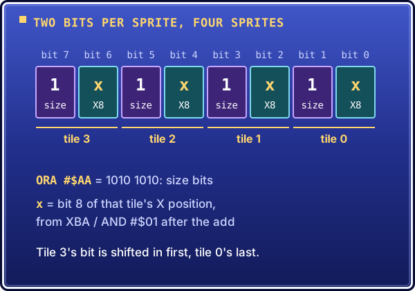
The byte Sub_C6E7 returns: two bits per sprite, X bit 8 in the even bits and the size bit, set by ORA #$AA, in the odd ones.
Decoding it means reading in strict M-flag order. Every LDA.w $4BXX,X is 16-bit (M=0) and every STA.w $4BXX,X is 8-bit (M=1), so EB (XBA) right after 9D xx 4B (STA abs,X) and before 29 01 (AND #$01) looks odd until you track the flag. 65 C3 (ADC $C3) is a 2-byte dp instruction doing a 16-bit add, because M=0.
Sub_C73A: the 6-tile type 3+ renderer
Sub_C73A at $C0:C73A–$C989 (592 bytes) is where Sub_B701 sends sprites of type 3 and up. It has the same layout as Sub_B788, scaled to 24 tiles:
Prologue:         PHB / LDA #$7F / PHA / PLB         → DB=$7F
Load:             LDX $6D / LDA.l $A80 / $A00 / $1700 → $C5/$C3/gfx_idx
6× JSR Sub_C6E7: one call per OAM slot (4 tiles each) → X-pos bytes written
Y-clamp:          3-way dispatch on $C6/$C5            → 24 Y-pos bytes written
Epilogue (×3):    PLB / RTS
After loading gfx_index (LDA.l $001700,X / TAX), it calls Sub_C6E7 six times. Between calls 1–5:
JSR Sub_C6E7        ; exit M=1, A=OAM byte, X=gfx_index
STX $D9             ; save gfx_index
LDX $6D             ; load OAM slot
STA.w $4F00,X       ; (or $4F01, $4B40, $4B41, $4F80) store OAM byte
LDX $D9             ; restore gfx_index
REP #$20
TXA
CLC
ADC #$0020          ; advance gfx_index by $20 (4 tiles × 8 bytes)
TAX                 ; X = new gfx_index
After call 6 (which writes $4F81) it resets gfx_index for the Y pass:
LDX $6D             ; reload OAM slot (not $D9)
REP #$20
LDA.l $001700,X     ; reload original gfx_index from sprite table
TAX
SEP #$20            ; back to M=1 for Y-dispatch
The six OAM bytes go to $7F:4F00,X, $7F:4F01,X, $7F:4B40,X, $7F:4B41,X, $7F:4F80,X and $7F:4F81,X. Six calls × 4 tiles = 24 tiles of X positions; the Y pass then walks the same 24 tiles. The two passes are independent.
| Condition | Path | Tiles | Clamp logic |
|---|---|---|---|
$C6 ≠ 0 |
Unrolled, 24 inline blocks | 24 | BCS → $E0 or BMI → $E0; only 0–$7F passes |
$C6 = 0, $C5 ≥ $80 |
Loop × 24 | 24 | None — raw add, result wraps |
$C6 = 0, $C5 < $80 |
Loop × 24 | 24 | BPL → store; BCS → store; else → $E0 |
The dispatch uses BMI where Sub_B788 uses BPL: if $C5 ≥ $80, BMI goes to the no-clamp loop; otherwise it falls through to a BRL to the clamp loop. The game uses bit 7 as a "large Y" flag, not as a sign.
One block of the unrolled $C6 ≠ 0 path (tile 0 of 24):
LDA.w $4BC4,X
CLC
ADC $C5
BCS .cl      ; overflow → clamp
BPL .st      ; 0–$7F → store as-is
.cl: LDA #$E0
.st: STA.w $4BC1,X
; ... 23 more identical blocks advancing source/dest by $08 each
Sources run $4BC4, $4BCC, $4BD4, …, $4C7C and destinations $4BC1, $4BC9, $4BD1, …, $4C79, step 8: the Y fields of 6 OAM slots × 4 tiles.
| Sub_B788 | Sub_C73A | |
|---|---|---|
| OAM slots | 1 | 6 |
| Tiles total | 4–5 | 24 |
| X-fill | Inline loop (3 iters) | 6× JSR Sub_C6E7 |
| Y-clamp loops | 4–5 tile unrolled | 24-tile counted loop (or unrolled) |
| Dispatch branch | BPL/BMI | BMI/BRL |
The sprite init helpers
Sub_B701 also runs init helpers before a sprite is first drawn. The game runs the init pass once per sprite spawn and the render pass every frame while the sprite is visible, and the state byte at $7F:1B00+X decides which runs.
Sub_B8CA: type 0 init, and a branch asymmetry
Sub_B8CA at $C0:B8CA–$BA64 (411 bytes) fills the staging buffer that Sub_B788 reads every frame. It has the same DB = $7F prologue and does three things:
- X-init loop. Walks the four tiles from
gfx_index+$18down togfx_index. For each, it copies the 16-bit raw X offset from$7F:4802,Xto$7F:4BC2,X, adds the base X ($C3), stores the low byte at$7F:4BC0,X, and takes the overflow bit (X bit 8) withXBA / AND #$01, packing the bits with shift-and-OR. - OAM attribute byte. After the loop,
ORA #$AAsets the large-sprite bits (positions 1/3/5/7) and the byte goes to$7F:4F00,X. It tells the PPU each tile's size and which tiles extend past X=256.Sub_B788builds the same kind of byte the same way. - Y-clamp pass. The same three-way dispatch as
Sub_B788andSub_C73A. Each path copies raw Y sources from$7F:4804,Xand so on into$7F:4BC4,X, computesY_source + $C5, clamps, and writes$7F:4BC1,X. The 16-bit Y-source copies ($4806,X→$4BC6,Xand so on) run in a shared epilogue on every path.
I decoded it from the raw bytes, tracing the M flag from the entry, without assuming the branch directions of earlier routines. That mattered:
| Path | Branch at C5 dispatch | Clamp branches |
|---|---|---|
Sub_B788 C6=0 |
BPL → positive |
BPL+4 / BCS+2 (both paths) |
Sub_B8CA C6=0 |
BPL → positive |
BCC+6 / BCC+2 (neg) vs BPL+6 / BCS+2 (pos) |
Sub_C73A C6=0 |
BMI → no-clamp |
BPL+2 / BCS+2 (both paths) |
The C6=0 dispatch is BPL in both Sub_B788 and Sub_B8CA, but the negative path's clamp differs completely. Sub_B788 uses BPL to skip the clamp. Sub_B8CA uses two BCCs: one to jump to the store (no overflow), one to skip LDA #$E0 (value < $E0).
The C6≠0 path differs again: BCC to the clamp (no overflow → $E0), then CMP #$E0 / BCS to store as-is when the wrapped value is in $E0–$FF. "Carry clear" here means "result too small, hide it off-screen". That makes sense once you see that C6≠0 means the 9-bit Y offset is at least $100, so nearly every tile overflows, and the only ones kept are those that wrap into $E0–$FF, near the bottom edge.
Byte-exact matching catches exactly this. Writing BCS where the code has BCC would flip one byte, and the bug would only show when a certain sprite type sits at a certain Y position.
Sub_E9E2: a search with a dead load
Sub_E9E2 at $C0:E9E2–$E9FE (29 bytes) is the type 0 "pass 2" helper. It searches a 4-entry table at $0BC0 for the current sprite slot (dp $6D) and writes $80 to the matching entry. No match, no change. It sets SEP #$10 (8-bit X) at entry, runs a counted loop, and does REP #$10 before each RTS.
It opens with LDX $6D followed at once by LDX #$00. The first load is dead: its value is thrown away before the loop starts. That is what a compiler emits when a variable initializer and a loop counter reset end up next to each other, something like int i = slot; for (i = 0; i < 4; i++). It is in the ROM, so it is in the source.
Sub_BA65: type 1 low-state init, and the BMI-split
For type 1 there are two init paths. A high-state path (Sub_BCDC) does the full table-read init. A low-state path (Sub_BA65) runs when the state hasn't crossed the high threshold. The difference is where they read X offsets: Sub_B8CA reads the raw table at $7F:4802,X; Sub_BA65 reads the staging buffer at $7F:4BC2,X, which an earlier init call already filled. Sub_BA65 continues Sub_BCDC's work; it doesn't replace it.
Sub_BA65 at $C0:BA65–$BCDB (631 bytes) has two X loops where Sub_B8CA has one. Both walk tiles in reverse (8-byte stride), pack the overflow bits, and stop when the index hits a reference value. The first covers gfx_index and writes its byte to $7F:4F00,X; the second covers gfx_index+$20 (the sprite's second OAM slot) and writes $7F:4F01,X. Two OAM slots, two packed bytes. The BRL at $BAF9 (raw offset $0154, target $BC50) sends C6≠0 past both Y-clamp blocks to the third exit path, the same C6-first dispatch as Sub_B8CA.
The Y clamp is where it breaks new ground. The negative path (C6=0, C5≥$80) uses a plain CMP #$E0 / BCC clamp like Sub_B8CA. The positive path (C6=0, C5<$80) checks each tile's source value with BMI before the add:
LDA.w $4BC4,X
BMI .pos_b0       ; source ≥ $80: take branch, then ADC $C5, then fall through
CLC               ; source < $80: ADD then BCC to store (no overflow)
ADC $C5
BCC .pos_st0      ; no overflow → store as-is
BRA .pos_p0       ; overflow → skip to clamp check
.pos_b0:
CLC
ADC $C5
.pos_p0:
BPL .pos_st0      ; result positive → store
CMP #$E0
BCS .pos_st0      ; result ≥ $E0 → store
LDA #$E0          ; result in [-128, $E0) → clamp
.pos_st0:
STA.w $4BC1,X
Sources $00–$7F are small positive offsets; sources $80–$FF are "large" values that need the BPL guard first. The code splits the two instead of using one clamp. The goal is to match the bytes, not to explain the intent, but the structure is the same on all eight tiles of the positive path, which points to generated code rather than hand-tuned logic.
Sub_BCDC and Sub_E9FF: type 1 complete
Sub_BCDC at $C0:BCDC–$BFF1 (790 bytes) is the high-state init. High state means nothing is in staging yet: it reads the raw table at $7F:4802,X and writes both staging ($7F:4BC2,X) and output ($7F:4BC0,X) in the same pass. Its X loop is LDA $4802,X / STA $4BC2,X / CLC / ADC $C3 / SEP #$20 / STA $4BC0,X: two stores per tile. Sub_BA65's loop is LDA $4BC2,X / CLC / ADC $C3 / SEP #$20 / STA $4BC0,X: one store, reading staging that already exists. You can't run the low-state path until the high-state path has run. The Y clamp also copies raw to staging (LDA $4804,X / STA $4BC4,X) before adding $C5.
The BMI-split is not there. Each tile goes straight to the add and then BPL/CMP/BCS:
LDA $48XX,X      ; source from raw table
STA $4BXX,X     ; copy to staging
CLC
ADC $C5
BPL .store       ; positive result → store as-is
CMP #$E0
BCS .store       ; negative but ≥$E0 (off-screen bottom range) → store
LDA #$E0         ; negative and <$E0 (wrapped into visible range) → clamp
.store: STA $4BC1,X
The C5 dispatch polarity flips too: BPL → positive in Sub_BA65 (branch if C5 bit 7 clear), BMI → negative in Sub_BCDC (branch if C5 bit 7 set). Same signal, opposite polarity.
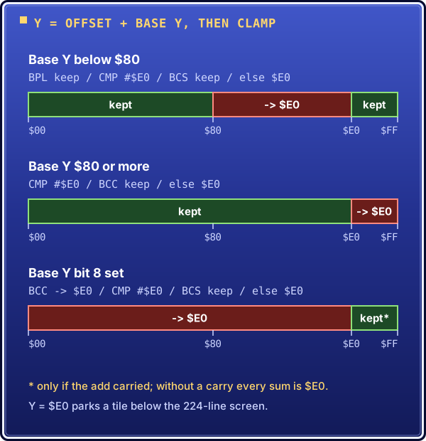
The three Y clamps of Sub_BCDC as number lines over the 8-bit sum. The same CMP #$E0 keeps different ranges depending on the branches around it, which is why each ordering has to be read from the bytes.
Sub_E9FF at $C0:E9FF–$EA1E (32 bytes) is the type 1 pass-2 helper. It parallels Sub_E9E2 with two differences:
| Sub_E9E2 (type 0) | Sub_E9FF (type 1) | |
|---|---|---|
| Loop limit | CPX #$04 (indices 0–3) |
CPX #$03 (indices 0–2) |
| Match action | STA.w $0BC0,X |
STA.w $0BC0,X + STA.w $0BC1,X |
Type 1 sprites use two OAM slots (one for gfx_index, one for gfx_index+$20), so pass 2 marks two entries. The smaller table (3 vs 4) likely reflects one fewer type 1 sprite. The dead LDX $6D / LDX #$00 pair is here too. Both functions matched byte-exact on the first try, and type 1 (Sub_BA65, Sub_BCDC, Sub_E9FF) is complete.
Sub_BFF2: types 2/3+ low-state init
Sub_BFF2 at $C0:BFF2–$C2BE (717 bytes) opens like every init helper: PHB, DB = $7F, REP #$20, entity index from $6D, coordinates from $0A80 and $0A00, anchor index from $1700, STZ $E5. Then it reads straight from staging ($4BC2), like Sub_BA65: low state.
It adds a third X loop. Sub_BCDC and Sub_BA65 build packed bytes for $4F00 and $4F01; Sub_BFF2 adds $4B40. Each loop runs backward from $18 above its base, step 8, to the base. The bases are $D9, $D9+$20 and $D9+$40: three OAM ranges, 12 tiles. The three loop bodies are byte-identical.
After the loops: LDX $D9, then the C6/C5 dispatch. $C6 != 0 long-branches to the type 3+ handler. Then BMI on $C5, as in Sub_BCDC (not BPL as in Sub_BA65): negative falls through to the simple path, positive branches long. Two BRLs with raw offsets $0143 and $006E, measured from the byte after the instruction.
There are three Y paths, not two:
- Negative (C5<0,
$C6=0): twelve plain adds, staging Y source plus$C5, no clamp. Eight tiles in the$4BC4/$4BC1family, then four more in a$4C04/$4C01block. These sprites are three tiles wide, so staging runs into a second 32-byte page. - Positive (C5≥0,
$C6=0):BPL → skip, CMP #$E0, BCS → skip, else LDA #$E0, twelve times. That is the BMI-split clamp fromSub_BA65, extended from 8 tiles to 12. - Type 3+ (
$C6≠0): new.BCSfirst, thenBPL. A carry from the add clamps to$E0regardless of sign; with no carry, a negative result also clamps. Only no carry plus positive keeps the value. That makes three different carry/sign orderings in the matched set, and none can be inferred from another.
So the BMI-split is not a one-off. Sub_BA65 (type 1, low state) and Sub_BFF2 (types 2/3+, low state) have it. Sub_BCDC (type 1, high state) and Sub_B8CA (type 0, high state) don't. It follows the low/high-state line, not the sprite type. The architecture doc used to say the BMI-split was "specific to Sub_BA65"; that paragraph is updated. make diff matched on the first assemble.
Sub_C2BF: a prediction that held
After Sub_BFF2, the prediction for Sub_C2BF (types 2/3+ high state) was: a raw $4802,X → $4BC2,X copy inside the X loops; C5 dispatch with BMI; a positive path that reads raw $4804,X, copies to $4BC4,X, then clamps with BPL/CMP/BCS and no BMI-split; 12 tiles. It held on every point.
The X loops diverge from Sub_BFF2 at once:
$C0:C2E4  BD 02 48      LDA $4802,X      ; raw table
$C0:C2E7  9D C2 4B      STA $4BC2,X      ; copy to staging   ← high-state marker
versus Sub_BFF2:
One quirk: an extra LDX $D9 at $C353 between the second and third loops, overwritten by TAX a few instructions later. Dead code, but the bytes need it. The dispatch:
$C0:C397  A5 C6         LDA $C6
$C0:C399  F0 03         BEQ .c2bf_c6_zero
$C0:C39B  82 23 02      BRL $C5C1        ; C6≠0 → nz path
.c2bf_c6_zero:
$C0:C39E  A5 C5         LDA $C5
$C0:C3A0  30 03         BMI .c2bf_neg    ; C5≥$80 → negative
$C0:C3A2  82 DE 00      BRL $C483        ; C5<$80 → positive
The three paths, in ROM order:
- Negative (
$C3A5–$C482): raw$4804,X → $4BC4,X, thenCLC/ADC $C5/STA, no clamp, 12 tiles. LikeSub_BFF2's negative path but reading raw. High state runs first and fills staging from raw; low state reads what it left. - Positive (
$C483–$C5C0): raw copy,CLC/ADC $C5,BPL/CMP/BCS, 12 tiles:Sub_BCDC's structure scaled to 12 tiles. - C6≠0 (
$C5C1–$C6E6): raw copy,CLC/ADC $C5,BCS → $E0 / BPL → keep, 12 tiles: the carry-first ordering fromSub_BFF2's type 3+ path.
All three end with the same twelve 16-bit pair copies ($4806→$4BC6, $480E→$4BCE, ..., $485E→$4C1E), then SEP #$20 / PLB / RTS. Sub_C2BF is 1,064 bytes ($C2BF–$C6E6), byte-exact on the first try. Two raw BRL offsets: $0223 ($C39B → $C5C1) and $00DE ($C3A2 → $C483). All short branches come from labels, and no .w suffix issues came up.
| Routine | State | Types | BMI-split? | Y-source in positive path |
|---|---|---|---|---|
| Sub_BA65 | low | 1 | yes | reads staging $4BC4,X |
| Sub_BCDC | high | 1 | no | reads raw $4804,X, copies to staging |
| Sub_BFF2 | low | 2/3+ | yes | reads staging $4BC4,X |
| Sub_C2BF | high | 2/3+ | no | reads raw $4804,X, copies to staging |
The difference is mechanical. High-state routines do the raw-to-staging copy themselves, so LDA raw / STA staging sits before the clamp. Low-state routines read staging directly, with no copy, and the BPL/CMP/BCS appears bare. "BMI-split" names that bare form.
Sub_EA1F, and the cluster is complete
An audit of every JSR, JSL, JMP and BRL in the sprite ranges ($B271–$C989, $E9E2–$EA1E) against the matched list found one unmatched callee: Sub_EA1F, the pass-2 helper for types 2/3+. Everything else was matched: Sub_B788, Sub_B8CA, Sub_BA65, Sub_BCDC, Sub_BFF2, Sub_C2BF, Sub_C6E7, Sub_C73A, Sub_E9E2, Sub_E9FF and Sub_B701 itself. The only stub was the Sub_EA1F label at line 3266.
Sub_EA1F at $C0:EA1F–$EA41 (35 bytes) took about ten minutes. Sub_E9E2 searches a 4-entry table and marks 1 byte; Sub_E9FF searches 3 entries and marks 2; Sub_EA1F searches 2 entries and marks 3 ($0BC0,X through $0BC2,X). The number of OAM bytes a type uses equals the number of table bytes marked. Same SEP #$10 / LDX #$00 / loop / REP #$10 / RTS skeleton, CPX #$02 and three STA.w on the found path.
The sprite cluster is complete. Execution can be traced from the VBlank interrupt through PostVBlank, Sub_B309 and Sub_B701 to the init helpers and renderers and back, with every branch explained by matched code. The architecture doc has a "Sprite System Overview" section, and there is a new sprite-init explainer covering the high/low-state split, the staging buffer, the Y-clamp orderings and the type/state matrix.
The high/low-state split is the central result. It took six routines across two type pairs to confirm: the BMI-split on the positive Y path marks low state, its absence marks high state. After Sub_BA65 it looked like a quirk; after Sub_BFF2, a pattern; with the cluster closed, it is a confirmed design property of the engine. (Two later notes size the cluster differently. One says what looked like three or four small functions became a 6,800-byte cluster once every callee was traced. The other puts it at about 4,600 bytes across 11 functions.)
The disassembler's M-flag trap, fixed
The trap caught me twice, in Sub_C73A and Sub_B8CA. tools/disasm.py tracked the M flag while walking forward. When a loop ended with REP #$20 and a BRA back, but had a BEQ exit that jumped past the REP, the decoder carried on through the fall-through, set M=0, and arrived at the exit target with the wrong state. The already-visited check then kept the correctly queued state from being processed. The symptom: 09 AA decoded as ORA #$AA6A (16-bit immediate) instead of ORA #$AA, and garbage after it. At the BEQ target the branch is taken from inside the loop after SEP #$20, so M=1.
The workaround was to re-derive the M state by hand at every loop exit. The real fix is in the is_branch handler: it used to queue the branch target and keep decoding linearly. Now it queues both the target and the fall-through as separate work items, each with the M/X state at the branch, and stops the linear scan. About ten lines. The architecture doc has a subsection under disasm.py on the cause, the two affected routines and the fix. The next two functions decoded with no operand-width errors, the first time I trusted the output without a manual M-state check.
Sub_0C76: the per-frame state machine
The next per-frame call after FrameStateInit is $C0:0C76. Early scouting said "200+ bytes, at least 6 unmatched callees, a JSL into bank $FD, a call to $881E, a TCD trick setting DP=$2100, and a BRL back to $0000 for a soft reset", and a second look added "BRLs to $D200". That last detail was wrong: there is no BRL to $D200. The real BRL targets are $0000 (warm boot), $0D3E (bit-4 dispatch), $19C7, $2824, $16DC, and six mode-handler blocks between $0D78 and $1454.
python3 tools/disasm.py roms/chrono_trigger.sfc C0 0C76 traced 17,814 unique addresses. The reason is the BRL at $0CC4: bytes 82 39 F3, offset $F339 = −3271, PC after = $0CC7, target $0000, the start of the GameLoop table. Following it re-traces the whole engine, so most of those addresses are old ground.
The head block is $0C76–$0D77, 258 bytes: the scroll-flag dispatcher, the countdown/warm-boot path, the fade-in loop, the color-transition setup and the mode-value dispatch. Its own callees:
Sub_1F24(54 bytes, leaf): scroll-X tracker. Moves dp$19(low nibble) toward the target in dp$1B, using dp$1Cas a step delay. Clears bit 1 of dp$18when it arrives.Sub_1F5A(45 bytes, leaf): the same for scroll Y. Moves dp$21toward dp$22, uses dp$23/$24, clears bit 3 of dp$18.
The other callees ($881E, $EC60, $011B, $01A5, $B192, $28C0, $FDFFF7, $C28000) only appear as call operands, so their bytes don't depend on being matched. The rule I applied: match the head if it plus its callees fits in ≤500 bytes with ≤3 new implementations. It came to 357 bytes (258 + 54 + 45) and 2 callees.
At $0D45–$0D77 the head reads the current mode from $7E3000,X and BRLs to one of six handlers: $0D78 ($E6), $0E5F ($EC), $1014 ($EE), $11C9 ($FA), $1454 ($FC) and $16DC (default). Every cross-block BRL needs a raw offset:
| BRL at | Target | PC after | Raw offset |
|---|---|---|---|
| $0CC4 | $0000 | $0CC7 | $F339 (−3271) |
| $0D06 | $19C7 | $0D09 | $0CBE |
| $0D3B | $2824 | $0D3E | $1AE6 |
| $0D42 | $16DC | $0D45 | $0997 |
| $0D56 | $0D78 | $0D59 | $001F |
| $0D5D | $0E5F | $0D60 | $00FF |
| $0D64 | $1014 | $0D67 | $02AD |
| $0D6B | $11C9 | $0D6E | $045B |
| $0D72 | $1454 | $0D75 | $06DF |
| $0D75 | $16DC | $0D78 | $0964 |
The BRL from $0CCB to $0D3E stays inside the same org $C00C76 block, so a local label (.chk_bit10) works. One tricky byte: $0CC2 = 06 9A is ASL $9A (direct page), not TXS. The LDX #$FF before it is unrelated to the stack pointer.
Quick wins that weren't quick
Scouting called $2824 (35 bytes, ending in RTS) and $19C7 (39 bytes, ending in RTI) quick wins. Both estimates were off.
Sub_2824($2824–$2847, 36 bytes) calls$286C(a scene-init probe). If it returns zero, the routine loops up to 15 VBlanks. Each pass increments dp$19, saves dp$1F, calls$881E(frame DMA/controller update) with$1Fzeroed, restores$1F, calls VBlankHandlerShort ($00DE) and$EC60. When dp$19reaches$0Fthe loop ends withSTZ $1EandSTZ $0407. A counted fade-in across exactly 15 VBlanks.Sub_19C7($19C7–$1A02, 60 bytes) is not a 39-byte RTI stub. It is a full mode-5 warm restart:InitHW,JSL $C28000with A = 5 (corrected later: that is the bank$C2menu's entry, not a BG mode switch), reinstall NMI/IRQ, DP=$0100, call$01A5and$1A03, move bit 6 from dp$17to dp$18if needed, call$B192, thenSub_2824for the fade. It ends withSTZ $0407andRTS.
Since Sub_19C7 calls Sub_2824, Sub_2824 had to be defined first in the file.
The mode handlers
ModeE6_Handler
ModeE6_Handler ($0D78–$0E5E, 231 bytes) runs when the current layer's mode byte is $E6. Three phases:
- Mode table update. Increments the layer's mode (
$E6→$E7) in$7E:3000,X. Then, in 16-bit A, finds the previous layer (X −$0100), reads its mode as a word, increments it and writes it back. Both layers advance together. - SPC audio trigger.
STZ $60clears a layer counter, thenJSR Sub_1B90.Sub_1B90(23 bytes, leaf) loads two bytes from dp and a table ($0A00+dp$97), writes them to$1E00–$1E02, and callsJSL $C70004, the SPC700 driver entry. A sound cue fires on the transition; which sound lives in bank$C7. - 8 VRAM tilemap indexes. Loads two scroll bases from
$1D0Aand$1D0Einto dp$DBand$DD, then runs two 4-point passes. Each computes a tile row (from dp$5B) and column (from dp$5C) and callsSub_1B36for the four corners of a 2×2 block: (col, row), (col, row+1), (col+1, row), (col+1, row+1). Pass 2 doesDEC Aon the column base first (col−1). Results go to$09CA,$09CC, ...,$09D8.
This looks like scroll-map setup: telling the hardware where to fetch tilemap words, with two overlapping columns tracked for smooth horizontal scrolling.
Sub_1B36 ($1B36–$1B52, 29 bytes, leaf) does the index math: 5× ASL (×32), save to dp $D9, then TYA; if row < 32 return row + col×32, otherwise (row−32) + col×32 + $0400. That encodes a 32×64 tilemap split over two VRAM pages at $0000 and $0400.
Sub_1B36 is called with M=0 but has no REP #$20 of its own. Because asar tracks M in file order, placing it after a SEP #$20 would assemble its CMP #$0020 as 2 bytes instead of 3. The fix: split ModeE6_Handler into two org blocks, header ($0D78–$0DA0) and computation ($0DA1–$0E5E), with Sub_1B36's block between them, so the header's REP #$20 carries into both.
ModeEC, ModeEE, ModeFA and ModeFC
The prediction that the other handlers share Sub_1B36 and Sub_1B90 was confirmed at once. All four matched byte-exact:
| Handler | Addr | Bytes | Description |
|---|---|---|---|
ModeEC_Handler |
$C0:0E5F | 437 | 4 mode-table updates, 4×4-corner VRAM pass |
ModeEE_Handler |
$C0:1014 | 437 | 4 mode-table updates, 4×4-corner VRAM pass (negative row) |
ModeFA_Handler |
$C0:11C9 | 651 | 6 mode-table updates, 6×4-corner VRAM pass |
ModeFC_Handler |
$C0:1454 | 648 | 6 mode-table updates, 6×4-corner VRAM pass (negative row) |
(Scouting had guessed about 112 bytes for ModeEC; it is 437.) All five handlers, $0D78–$16DB, follow one two-phase template:
Phase 1, prologue. Increment entries in the $7E:3000 layer table. The count and the INX/DEX/REP/SBC/TAX/SEP blocks scale with the mode: E6 2 entries (1 SBC block), EC/EE 4 (1 SBC block), FA/FC 6 (2 SBC blocks). All but E6 then call JSR Sub_1B90 (SPC command $19) and write dp $60, which encodes the scroll width: $00 2-entry, $01 4-entry, $02 6-entry.
Phase 2, VRAM. A REP #$20 block sets dp $DB/$DD from $1D0A/$1D0E (scroll X/Y bases). N passes each compute row and column, mask with AND #$003F / AND #$001F, and call JSR Sub_1B36 for the four corners (0,0), (1,0), (0,1), (1,1), using PHA/PLY to keep the row across the col+1 step. Results (plus ADC $1D7C) go to consecutive 2-byte slots from $09CA up.
| Handler | Row bases | Col bases | Total passes |
|---|---|---|---|
| ModeE6 | $5B | $5C, $5C−1 | 2 |
| ModeEC | $5B, $5B+1 | $5C, $5C−1 | 4 |
| ModeEE | $5B−1, $5B | $5C, $5C−1 | 4 |
| ModeFA | $5B, $5B+1 | $5C, $5C−1, $5C−2 | 6 |
| ModeFC | $5B−1, $5B | $5C, $5C−1, $5C−2 | 6 |
EC and FA walk forward in row space; EE and FC walk backward.
Quirks to reproduce:
LDX $5Bon pass 1 only. Every handler's first pass opensLDX $5B; TXA(3 bytes) where later passes useLDA $5B(2 bytes). X is never used as an index here: a compiler artifact. In EE and FC the first pass also hasDEC AbetweenTXAandASL.Sub_1B90order. ModeEC setsLDA #$01; STA $60beforeJSR Sub_1B90; EE, FA and FC call first and set$60after.- ModeFC has no tail BRL. The others end with
SEP #$20; LDA #$10; TSB $5F; BRL <raw_offset>to the default handler at$16DC. ModeFC sits right before$16DCand falls through, so its tail is justSEP #$20; LDA #$10; TSB $5F(6 bytes).
The default handler: scoped for tomorrow
$C0:16DC is different from the five named handlers. It uses dp $5D/$5E for layer indexing (not $5B/$5C), stores VRAM results to $09B2–$09B8, sets bit 1 of dp $5F (not bit 4), never calls Sub_1B90, branches at entry on dp $17 bit 1 (BIT #$02; BNE), calls a new callee at $C0:1BA7 (right after Sub_1B90), loops calling $885A and $EC60 until dp $38 = $00, and has internal BRLs ($1770 secondary entry, $1862, $188C). Scouting first guessed about 432 bytes; the estimate is now $19C6 − $16DC + 1 ≈ 747 bytes.
The $0C76 cluster
The region $0C76–$2DF0 is too big to treat as single targets: an estimated ~8,600 bytes in 20+ blocks. It is now tracked as the $0C76 Per-Frame State Machine Cluster in the bank map, with a per-block status table, the same way the sprite cluster was tracked ("7 of 11 blocks done, 3 remaining"). Unlike the sprite cluster, its blocks can't all be listed yet: the region past $2DF1 is uncharted.
$881E and $18D9 at a glance
$881E(called from the frame loop,Sub_00EBandSub_0C76): body 60 bytes ($881E–$8859). Callees:$88E5(6 bytes, a trivial copy),$88EE(~20 bytes plus an indirectJSR), and$8A6D, whichBRLs to eight sub-blocks ($8AB5,$8BC4,$8BF9,$8D11,$8E21,$8EF1,$8FC1,$909C). 4,161 instructions in all. An earlier look had it at about 59 bytes calling seven unmatched routines ($88E5,$88EE,$8A6D,$9175,$99DE,$91AC,$93E1), probably DMA/PPU prep. Its head ($881E+$88E5+$88EE, ~86 bytes) is a realistic partial match.$18D9(the first call in GameLoop_FrameBody): 107+ bytes, calls$EC60,$1985and$1ADF, reads the NMI flag$00F0. 12,977 instructions traced. (An earlier look said about 60 bytes, callingSub_EC60andJSL $FDC2C1.)
Neither is a single-session target.
The day in numbers
| Session | Routine | Address | Bytes | Running total quoted |
|---|---|---|---|---|
| 4 | GameLoop spine and helpers (InitHW 22, InstallNMI 17, InstallIRQ 17, ClearRAMDMA 45, PostVBlank 152) | $C0:0000… |
536 | 1,009 (see note) |
| 5 | FrameStateInit |
$C0:0B86 |
240 | 1,247 |
| 7–8 | Sub_B701 (first measured as 171) |
$C0:B701–$B787 |
135 | |
| 8 | Sub_B309 |
$C0:B309 |
1,016 | 2,569 (see note) |
| 9 | Sub_B788 |
$C0:B788 |
322 | 2,891 |
| 10 | Sub_C6E7 |
$C0:C6E7–$C739 |
83 | 2,974 |
| 11 | Sub_C73A |
$C0:C73A–$C989 |
592 | 3,566 |
| 12 | Sub_B8CA |
$C0:B8CA–$BA64 |
411 | 3,977 |
| 13 | Sub_E9E2 |
$C0:E9E2–$E9FE |
29 | |
| 13 | Sub_BA65 |
$C0:BA65–$BCDB |
631 | 4,637 |
| 14 | Sub_BCDC |
$C0:BCDC–$BFF1 |
790 | |
| 14 | Sub_E9FF |
$C0:E9FF–$EA1E |
32 | 5,459 |
| 15 | Sub_BFF2 |
$C0:BFF2–$C2BE |
717 | 6,176 |
| 16 | Sub_C2BF |
$C0:C2BF–$C6E6 |
1,064 | 7,240 |
| 17 | Sub_EA1F |
$C0:EA1F–$EA41 |
35 | 7,275 |
| 18 | Sub_0C76 |
$C0:0C76–$0D77 |
258 | |
| 18 | Sub_1F24 |
$C0:1F24 |
54 | |
| 18 | Sub_1F5A |
$C0:1F5A |
45 | 7,632 |
| 19 | ModeE6_Handler |
$C0:0D78–$0E5E |
231 | |
| 19 | Sub_1B36 |
$C0:1B36–$1B52 |
29 | |
| 19 | Sub_1B90 |
$C0:1B90 |
23 | |
| 19 | Sub_2824 |
$C0:2824–$2847 |
36 | |
| 19 | Sub_19C7 |
$C0:19C7–$1A02 |
60 | 8,011 |
| 20 | ModeEC_Handler |
$C0:0E5F |
437 | |
| 20 | ModeEE_Handler |
$C0:1014 |
437 | |
| 20 | ModeFA_Handler |
$C0:11C9 |
651 | |
| 20 | ModeFC_Handler |
$C0:1454 |
648 | ~10,184 |
| Total | 9,542 |
Every routine was confirmed with make diff (4,194,304 bytes identical).
Two notes on the running totals quoted during the day. Session 4's notes say both "536 new bytes" and "1,009 total"; 471 + 536 is 1,007. The next session's bank figure (776 for $C0 = 536 + 240) follows 536, so the table uses that. And the running total after Sub_B309 (2,569) equals 1,247 + 1,016 + 171 + 135, so Sub_B701 seems to have been counted at both sizes. The table counts it once, at 135. The day closed with a quoted running total of ~10,184 bytes across banks $00/$C0/$FD (after session 19: 8,011 bytes, 32 functions, 7,540 bank $C0 bytes).
Next
The default mode handler at $C0:16DC (~747 bytes), which needs Sub_1BA7 at $C0:1BA7 identified first. Then $C0:881E (frame DMA/controller update, ~60-byte body with a large callee tree). The $0C76 cluster will take more sessions: bottom-up through the handlers, then the $881E tree, then $18D9.